Introduction
The Controller Area Network (CAN) is a vehicle standard initially designed by Bosch to allow the communication between microcontrollers from different ECUs (Electrical Control Units) inside a vehicle. The architecture is structured in a OSI model implementing the first two layers: Physical and Data link layers. The CAN bus evolved into two ISO standards: ISO11898-1, which covers the Data link layer, and the ISO11898-2, which covers the Physical layer (electric properties, etc). There are basically two types for the Physical layer of CAN bus:
Low speed CAN bus (also referred to as fault tolerant CAN): It enables low bit rate transfers, from 40 kbit/s to 125 kbit/s, but it can continue to work even if one of the two wires of the bus fail.
High speed CAN bus: Supporting bit rates from 40 kbit/s to 1 Mbit/s (Classical CAN) this is the most popular CAN bus standard and the base for upper layer protocols, such as OBDII, J1939, etc. The second generation of CAN is known as CAN with Flexible Data-rate, or CAN FD. This standard is also compatible with Classical CAN and enables bit rates up to 8 Mbit/s.
CAN bus on Linux
The Linux kernel supports CAN network through the SocketCAN framework. For the matter of information, there is also an external open source driver called can4linux that supports many can controllers through a character device (for instance, /dev/can0). However, it will not be discussed here since the standard and official SocketCAN kernel interface also supports many controllers, it’s maintained by kernel developers and shall be supported by EVE.
SocketCAN is built upon the Linux network layer, so CAN interfaces are listed as network interfaces in the system, as shown below:
$ ip addr show can0
7: can0: <NOARP,ECHO> mtu 16 qdisc noop state DOWN group default qlen 10
    link/can
Therefore, the communication is performed through sockets. The regular network system tools, like ifconfig or ip can be used to setup CAN interfaces, and other userspace utilities can be used to send and receive CAN data. These are the settings for a CAN interface:
$ ip link set can0 type can help
Usage: ip link set DEVICE type can
	[ bitrate BITRATE [ sample-point SAMPLE-POINT] ] |
	[ tq TQ prop-seg PROP_SEG phase-seg1 PHASE-SEG1
 	  phase-seg2 PHASE-SEG2 [ sjw SJW ] ]

	[ dbitrate BITRATE [ dsample-point SAMPLE-POINT] ] |
	[ dtq TQ dprop-seg PROP_SEG dphase-seg1 PHASE-SEG1
 	  dphase-seg2 PHASE-SEG2 [ dsjw SJW ] ]
	[ tdcv TDCV tdco TDCO tdcf TDCF ]

	[ loopback { on | off } ]
	[ listen-only { on | off } ]
	[ triple-sampling { on | off } ]
	[ one-shot { on | off } ]
	[ berr-reporting { on | off } ]
	[ fd { on | off } ]
	[ fd-non-iso { on | off } ]
	[ presume-ack { on | off } ]
	[ cc-len8-dlc { on | off } ]
	[ tdc-mode { auto | manual | off } ]

	[ restart-ms TIME-MS ]
	[ restart ]

	[ termination { 0..65535 } ]

	Where: BITRATE	:= { NUMBER in bps }
		  SAMPLE-POINT	:= { 0.000..0.999 }
		  TQ		:= { NUMBER in ns }
		  PROP-SEG	:= { NUMBER in tq }
		  PHASE-SEG1	:= { NUMBER in tq }
		  PHASE-SEG2	:= { NUMBER in tq }
		  SJW		:= { NUMBER in tq }
		  TDCV		:= { NUMBER in tc }
		  TDCO		:= { NUMBER in tc }
		  TDCF		:= { NUMBER in tc }
		  RESTART-MS	:= { 0 | NUMBER in ms }
- bitrate: CAN interface’s bit rate (bps)
- sample-point: Point in time period where the bus is read to get the current bit level
- tq: Time Quantum (1 TQ = 1 Clock tick). Each bit in the CAN bus consists in four non-overlapped time segments:
- sync-seg: Comprises 1 TQ for synchronization
- prop-seg: Compensates the propagation of physical delays between nodes
- phase-seg1 and phase-seg2: Both are used to compensate errors between signal edges and adjust the length of the bit
- Note: All these properties are expressed in numbers of TQ
- sjw: Synchronization jump width, that’s the maximum time by which the bit sampling period might be delayed or shortened during each cycle
- dbitrate: Data bit rate (used in CAN FD, which supports different bit rates for the arbitration phase and the data/payload phase)
- dtq: Data Time Quantum (used in CAN FD). Like the nominal bit time, the Data Bit Time comprises the same four time segments, so the same properties are supported (in numbers of DTQs)
- tdcv: Transmitter Delay Compensation Value (used in CAN FD)
- tdco: Transmitter Delay Compensation Offset (used in CAN FD)
- tdcf: Transmitter Delay Compensation Filter windows value (used in CAN FD)
- loopback: Used specially when running more than one application on the same node (host). Due to the arbitration of the CAN bus, some loopback is needed to ensure the communication will work in the same way as the applications were running into dedicated nodes
- listen-only: Only listen for frames on the bus (no sending)
- triple-sampling: Make 3 samples instead of 1 during the bit time (on the 2 TQs before the Sample Point)
- one-shot: Just send the CAN message one time (skip retransmission in case of error)
- berr-reporting: Enable/Disable Bit Error reporting
- fd: Enable/Disable the CAN FD (flexible data rate)
- fd-non-iso: Enable non-ISO CAN FD (this is the first specification of CAN FD, called CAN FD 1.0 and it’s not compatible with ISO CAN FD[10])
- presume-ack: When enabled, acknowledgement absence is ignored
- cc-len8-dlc: DLC remaining seven values from 9 to 15 used for CAN FD should be set to 8 for standard CAN.
- tdcv-mode: Transmitter Delay Compensation Value mode (automatic, manual or disabled - used in CAN FD)
- restart-ms: Automatic restart delay time, the time to wait before restart the CAN controller in case of a bus-off condition (a CAN node becomes Bus-Off when the the counter for transmission errors becomes greater or equal to 256, so the node is deactivated[12])
- restart: Restart the CAN interface (it will also create a CAN Error Frame)
- termination: Enable/Disable terminating resistor
The CAN bus is clock based so the majority parameters of the controller are related to the CAN Bit timing properties. Some of the described parameters should also be supported by the CAN controller in order to be configured.
Software Setup
The quickest way to test CAN interfaces is the use of the userspace tools from can-utils package, which can be done through the following steps:
Install can-utils package (Debian based) and setup CAN interfaces:
$ apt install can-utils
$ ip link set can0 type can bitrate 125000
$ ip link set can0 up
The candump utility shows packages received on a given CAN interface:
$ candump can0
  can1  123   [8]  11 22 33 44 55 66 77 88
The cansend utility can be used to send data through a given CAN interface:
$ cansend can0 123#1122334455667788
Setup a virtual CAN interface
A virtual CAN interface is created also using iproute:
$ ip link add dev vcan0 type vcan
After the creation, the setup is exactly the same as a physical CAN:
$ ip link set vcan0 type can bitrate 125000
$ ip link set vcan0 up
CAN Virtualization
QEMU supports CAN virtualization. A VM with access to the host’s CAN interface can be initialized through QEMU using parameters like the following:
#/bin/bash

IMGFILE=/var/lib/libvirt/images/Ubuntu-VM.qcow2

qemu-system-aarch64 \
	-display none \
	-serial stdio \
	-smp 2 \
	-cpu cortex-a53 \
	-machine virt-7.2,accel=kvm \
	-m 800 \
	-d unimp -semihosting-config enable=on,target=native \
	-object rng-random,filename=/dev/urandom,id=rng0 \
	-device virtio-rng-device,rng=rng0 \
	-bios u-boot.bin \
	-drive if=pflash,file=nvram.img,format=raw,index=1 \
	-drive if=none,file=${IMGFILE},id=hd0 -device virtio-blk-device,drive=hd0 \
	-netdev bridge,br=virbr0,id=if1 -device e1000,netdev=if1 \
	-object can-bus,id=canbus0 \
	-device kvaser_pci,canbus=canbus0 \
	-object can-host-socketcan,id=canhost0,if=can0,canbus=canbus0
The important parameters from the reference above for CAN emulation are:
-object can-bus,id=canbus0 \
	-device kvaser_pci,canbus=canbus0 \
	-object can-host-socketcan,id=canhost0,if=can0,canbus=canbus0
They will create a virtual (emulated) CAN interface in the guest and connect it to the CAN interface can0 of the host. The controller emulated in the Guest is the Kvaser PCI CAN-S (single SJA1000 channel) board, which is supported by the mainline kernel. It’s important to point out that the CAN interface of the host has to be proper set up and powered up. The configuration from emulated devices is not propagated to the physical host interface[14].
The emulated CAN interface can be used inside the Guest just as a physical one:
# To be executed on the guest
$ ip link set can0 type can bitrate 125000
$ ip link set can0 up
$ cansend can0 123#1122334455667788
QEMU VM configuration file
CAN emulation can be configured like the following in the VM’s configuration file:
[object "canbus0"]
  qom-type = "can-bus"

[device "can0"]
  driver = "kvaser_pci"
  canbus = "canbus0"

[object "canhost0"]
  qom-type = "can-host-socketcan"
  canbus = "canbus0"
  if = "can0"
Introducing CAN support on EVE
The goal of introducing CAN bus support on EVE is to allow the deployment of Edge Applications that use CAN interfaces. Enabling also the Virtual CAN in the host allow supporting complex use cases, such as those where a CAN proxy can be implemented between the Guests running on the system.
Requirements
The general requirements for CAN bus support on EVE are expressed on Table 2. Differently from the PCI passthrough, the access to the CAN interfaces present in the host by Guests are allowed by QEMU through an emulated device, like is done for other devices, such as Serial Ports. However, for the simplicity of the text, the term passthrough will be used as of now interchangeable. In summary, passing-through a CAN interface means that Guests will be able to access this interface through the emulated device.
Table 2: General requirements for CAN support on EVE
Requirement | Description |
|---|---|
R.1 | CAN bus should be supported by EVE’s kernel |
R.2 | EVE should support CAN controllers present in the hardware |
R.3 | EVE should support Virtual CAN interfaces |
R.4 | EVE should be able to configure CAN interfaces (physical or virtual) and set all parameters supported by iproute2 |
R.5 | EVE should be able to passthrough one or more CAN interfaces (physical or virtual) to one or more Edge Applications, i.e., containers and/or VMs |
R.6 | EVE should get the configuration for CAN interfaces (physical or virtual) from the device model |
R.7 | EVE should not allow dynamic adding/removal of virtual CAN interfaces |
Table 3 presents the specification of each requirement from Table 2.
Table 3: Requirements for CAN support on EVE
Requirement | Description |
|---|---|
RS.1 | CAN bus should be supported by EVE’s kernel The SocketCAN Framework must be built/enabled in the kernel. |
RS.2 | EVE should support CAN controllers present in the hardware All the devices officially supported by EVE and equipped with CAN controllers must have the corresponding device drivers built/enabled in the kernel (when available). Device drivers for USB CAN adapters can also be provided as modules. |
RS.3 | EVE should support Virtual CAN interfaces The Virtual CAN interface device driver should be built/enabled in the kernel (CONFIG_CAN_VCAN), as well as the drivers for QEMU’s CAN virtio devices:
|
RS.4 | EVE should be able to configure CAN interfaces (physical or virtual) and set all parameters supported by iproute2 EVE should be able to understand and setup the parameters described on Table 4. Notice that some CAN controllers, including the Virtual CAN, don’t support all the parameters, so only those specified in the configuration for a specific interface must be set by EVE. |
RS.5 | EVE should be able to passthrough one or more CAN interfaces (physical or virtual) to one or more Edge Applications, i.e., containers and/or VMs Pillar + Domain manager should generate the corresponding QEMU configuration for a VM/Container with all CAN interfaces with passing-through required. There will be no distinction between a Virtual and Physical CAN interface Notice that in opposite to other devices, like Serial Ports, the same CAN interface can be passed-through to more than one VM/Container. EVE must support such configuration. |
RS.6 | EVE should get the configuration for CAN interfaces (physical or virtual) from the device model The parameters of Table 4 should be specified for each CAN interface (to be used by EVE) in the device model (JSON format). Only the parameters that are supported by the CAN controller should be provided. EVE should not change/set any parameter that is not specified in the device model |
RS.7 | EVE should not allow dynamic adding/removal of virtual CAN interfaces The configuration for CAN interfaces (Virtual CAN, etc) are fixed in the device model, EVE should not change it, unless the device model is updated. EVE should proceed the following steps:
Any CAN interface that is not described in the configuration should be left untouched by EVE. EVE should not add/remove any Virtual CAN during runtime, unless the device model is updated. |
Table 4: Parameters of a CAN interface. Not all parameters should be supported by all controllers, including Virtual CAN
Parameter | Allowed values |
|---|---|
bitrate | NUMBER in bps |
sample-point | 0.000..0.999 |
tq | NUMBER in ns |
prop-seg | NUMBER in tq |
phase-seg1 | NUMBER in tq |
phase-seg2 | NUMBER in tq |
sjw | NUMBER in tq |
dbitrate | NUMBER in bps |
dsample-point | 0.000..0.999 |
dtq | NUMBER in ns |
dprop-seg | NUMBER in tq |
dphase-seg1 | NUMBER in tq |
dphase-seg2 | NUMBER in tq |
dsjw | NUMBER in tq |
tdcv | NUMBER in tc |
tdco | NUMBER in tc |
tdcf | NUMBER in tc |
loopback | on | off |
listen-only | on | off |
triple-sampling | on | off |
one-shot | on | off |
berr-reporting | on | off |
fd | on | off |
fd-non-iso | on | off |
presume-ack | on | off |
cc-len8-dlc | on | off |
tdc-mode | auto | manual | off |
restart-ms | 0 | NUMBER in ms |
restart | True | False |
termination | 0..65535 |
Use cases
This section describes the main use cases with different configurations and/or uses of CAN bus by Edge Applications and EVE-OS. In all examples it will be considered a hypothetical device running EVE-OS with three Edge Applications deployed (no matter their type, i.e., if they are Containers and/or VMs). However, all these examples can be expanded to different combinations and setups.
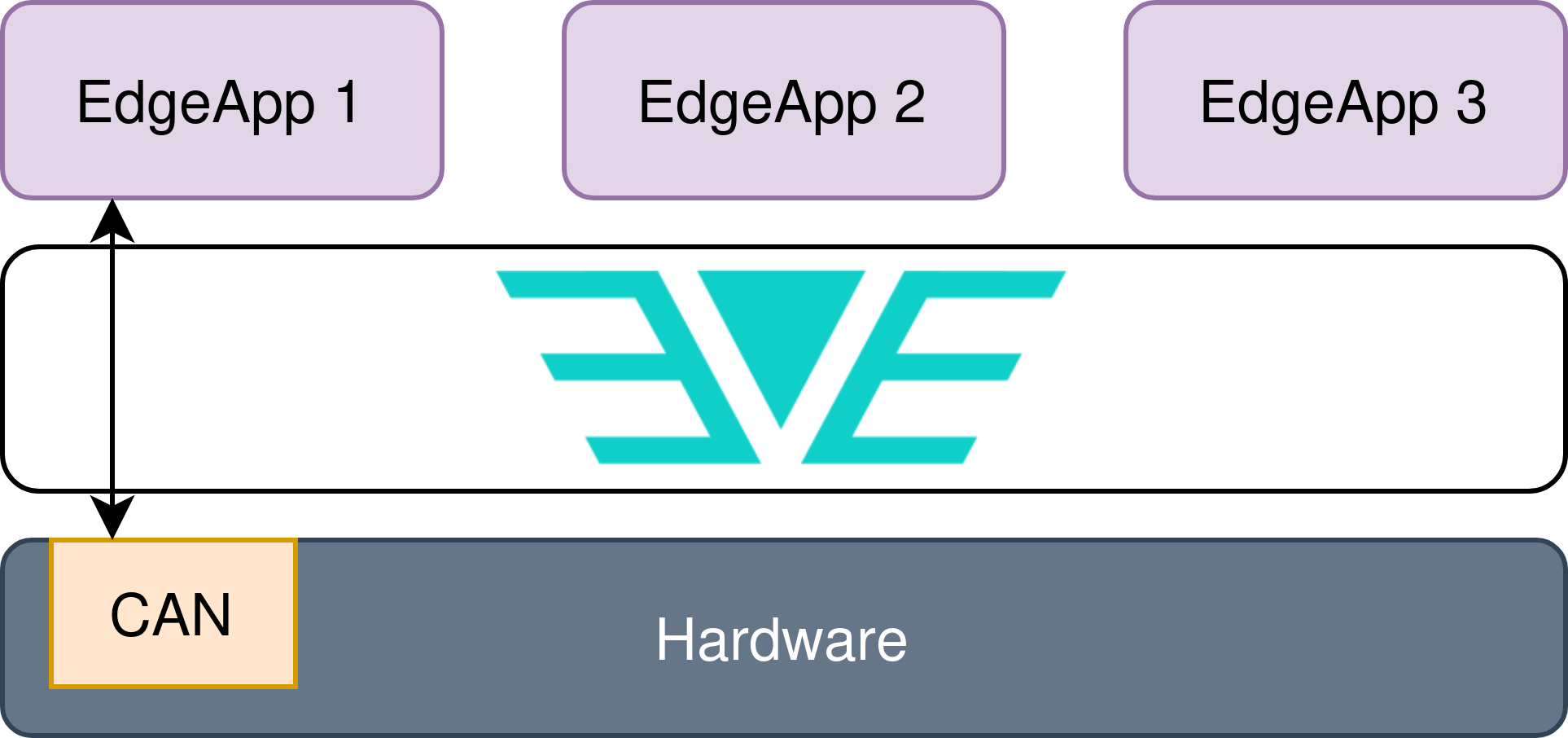
Fig. 1: Only one Edge Application has access to the physical CAN interface from the host.
In the use case of Fig. 1 the hardware is equipped with one physical CAN interface which is passed-through to the Edge Application EdgeApp 1. Thus, this Guest will have the physical CAN interface exposed through the emulated device provided by QEMU, so it should see a regular can interface (can0, for instance) through where the communication can be established.
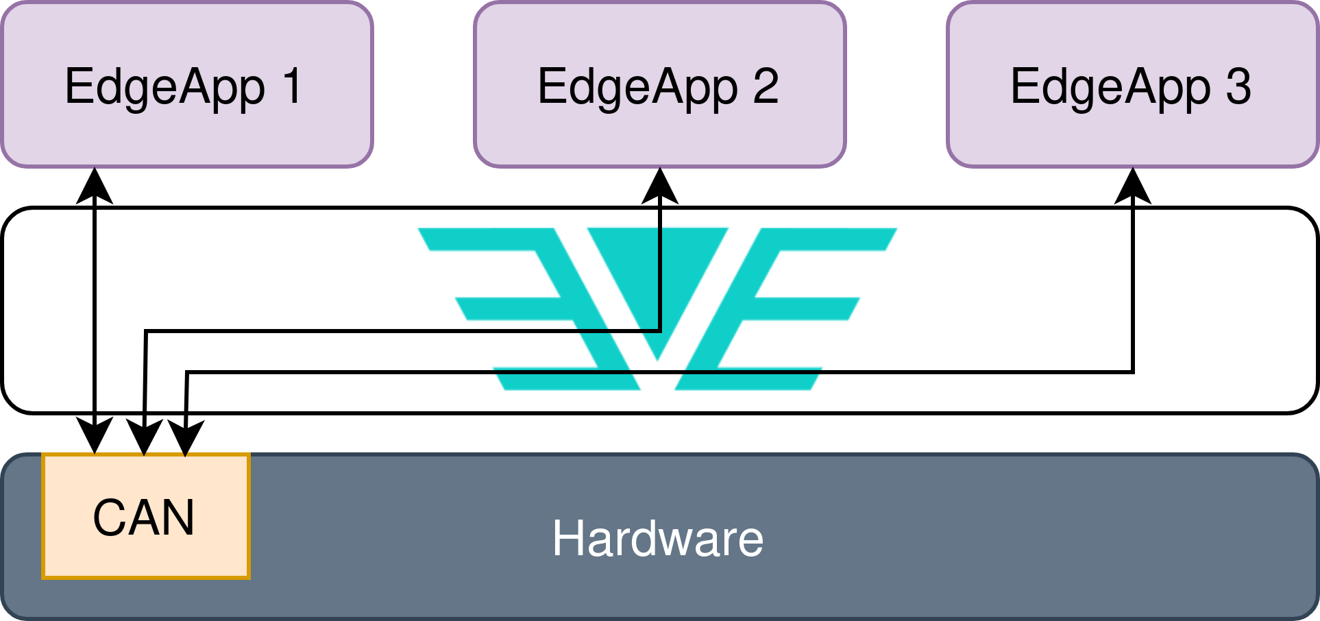
Fig. 2: All Edge Applications have access to the physical CAN interface from the host.
In the use case of Fig. 2 the hardware is equipped with one physical CAN interface which is passed-through to all Edge Applications deployed on the system (EdgeApp 1 to 3). In this case, all Guests should have the physical CAN exposed through the emulated device provided by QEMU. Due to the broadcast nature of the CAN bus, all frames sent to this interface shall be seen by all Guests.
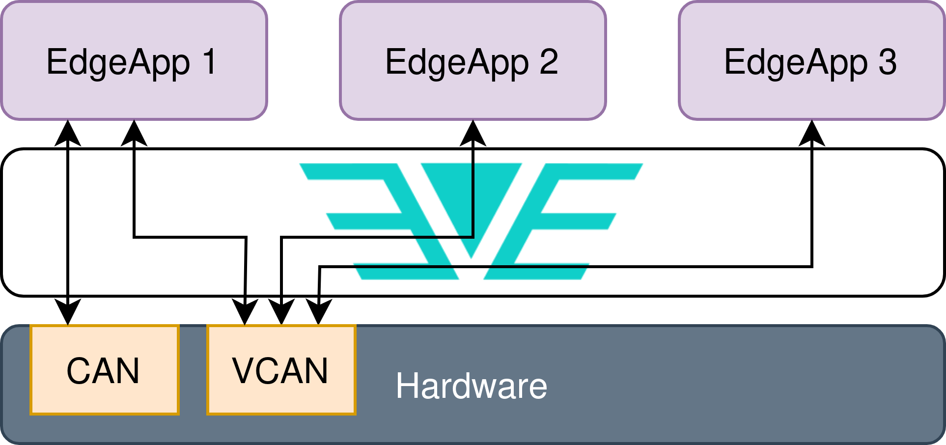
Fig. 3: One Edge Application has access to the physical CAN interface from the host and one virtual CAN interface, which is also accessed by the other two Edge Applications. In this case, EdgeApp 1 could act as a proxy between VCAN->CAN.
The use case of Fig. 3 illustrates a more complex scenario, where the hardware is equipped with one physical CAN interface and one Virtual CAN interface that is configured by EVE-OS. Both physical and virtual CAN interfaces are passed-through to EdgeApp1 while the Virtual interface is also passed-through to EdgeApp 2 and Edge App 3. In this setup the EdgeApp 1 could act as a proxy/firewall for the CAN bus traffic of EdgeApp 2 and EdgeApp3, forwarding only the desired frames to the physical CAN interface (on both directions, for instance).
Device model
CAN interfaces (physical or virtual) shall be specified in the Device Model file as members of the list of I/O devices (ioMemberList), for instance, a physical CAN interface (can0) can be configured by the following code:
"ioMemberList": [
	{
		"ztype": "IO_TYPE_CAN",
		"phylabel": "can0",
		"logicallabel" : "can0",
		"assigngrp" : "",
		"phyaddrs" : {
			"ifname" : "can0"
		},
		"cbattr" : {
			"bitrate": "125000",
			"sample-point": "0.875",
			"tq": "29",
			"prop_seg": "118",
			"phase_seg1": "119",
			"phase_seg2": "34",
			"sjw": "1",
			"dbitrate": "250000",
			"dsample-point": "0.875",
			"dtq": "29",
			"dprop_seg": "118",
			"dphase_seg1": "119",
			"dphase_seg2": "34",
			"dsjw": "1",
			"loopback": "on",
			"listen-only": "off",
			"triple-sampling": "off",
			"one-shot": "off",
			"berr-reporting": "on",
			"fd": "on",
			"fd-non-iso": "off",
			"presume-ack": "on",
			"cc-len8-dlc": "off",
			"tdc-mode": "auto"
		}
	}
]
The parameter ztype shall be:
IO_TYPE_CAN: For physical CAN interfaces
IO_TYPE_VCAN: For virtual CAN interfaces
IO_TYPE_LCAN: For a logical CAN device, i.e., this type of device doesn’t define any configuration for a CAN controller, but it just points to another (physical or virtual) CAN interface. It should be particularly used to duplicate a CAN interface in the device model so it can be passed-through to more than one Edge Application
Only the following parameters are mandatory:
ztype
phylabel
logicallabel
cbattr (at least bitrate should be present for IO_TYPE_CAN type)
Parameters not supported by the CAN interface shall be omitted from the device model file.
Cloud controller requirements
It’s important to point out that in case of CAN interfaces, the same CAN interface can be assigned to one or more Edge Applications. This requirement breaks the logic for device passthrough on EVE + Cloud Controller. So the alternative approach is to use the logical CAN definition, which points to a physical/virtual CAN interface in the device model. For instance, the use case from Fig. 1 would have the following configuration in the device model:
"ioMemberList": [
	{
		"ztype": "IO_TYPE_CAN",
		"phylabel": "can0",
		"logicallabel": "can0",
		"assigngrp" : "",
		"phyaddrs" : {
			"ifname" : "can0"
		},
		"cbattr" : {
			"bitrate": "125000",
		}
	},
	{
		"ztype": "IO_TYPE_LCAN",
		"phylabel": "can0.1",
		"logicallabel": "can0.1",
		"assigngrp" : "can0.1",
		"phyaddrs" : {
			"ifname" : "can0"
		},
	},
	{
		"ztype": "IO_TYPE_LCAN",
		"phylabel": "can0.2",
		"logicallabel": "can0.2",
		"assigngrp" : "can0.2",
		"phyaddrs" : {
			"ifname" : "can0"
		},
	},
	{
		"ztype": "IO_TYPE_LCAN",
		"phylabel": "can0.3",
		"logicallabel": "can0.3",
		"assigngrp" : "can0.3",
		"phyaddrs" : {
			"ifname" : "can0"
		},
	}
]
So logically the device is presented with 4 CAN interfaces, the physical (real) controller plus 3 logical interfaces, where each one can be passed-through to each Edge Application. However, all of them point to the same physical can0. In the device model, the interface can0 is the one that describes the physical CAN interface and contains the proper parameters to set up the controller. The logical interfaces can0.1, can0.2 and can0.3 point to can0 and can be passed-through the the applications.
The use case from Fig. 3 would have the following configuration in the device model:
"ioMemberList": [
	{
		"ztype": "IO_TYPE_VCAN",
		"phylabel": "vcan0",
		"logicallabel": "vcan0",
		"assigngrp" : "",
		"phyaddrs" : {
			"ifname" : "vcan0"
		},
		"cbattr" : {
			"bitrate": "125000",
		}
	},
	{
		"ztype": "IO_TYPE_LCAN",
		"phylabel": "vcan0.1",
		"logicallabel": "vcan0.1",
		"assigngrp" : "vcan0.1",
		"phyaddrs" : {
			"ifname" : "vcan0"
		},
	},
	{
		"ztype": "IO_TYPE_LCAN",
		"phylabel": "vcan0.2",
		"logicallabel": "vcan0.2",
		"assigngrp" : "vcan0.2",
		"phyaddrs" : {
			"ifname" : "vcan0"
		},
	},
	{
		"ztype": "IO_TYPE_LCAN",
		"phylabel": "vcan0.3",
		"logicallabel": "vcan0.3",
		"assigngrp" : "vcan0.3",
		"phyaddrs" : {
			"ifname" : "vcan0"
		},
	},
	{
		"ztype": "IO_TYPE_CAN",
		"phylabel": "can0",
		"logicallabel": "can0",
		"assigngrp" : "",
		"phyaddrs" : {
			"ifname" : "can0"
		},
		"cbattr" : {
			"bitrate": "125000",
		}
	},
	{
		"ztype": "IO_TYPE_LCAN",
		"phylabel": "can0.1",
		"logicallabel": "can0.1",
		"assigngrp" : "can0.1",
		"phyaddrs" : {
			"ifname" : "can0"
	    },
	}
]
Notice that only one interface should have the type IO_TYPE_VCAN, which is the one that creates the virtual interface on the system. The other interfaces that point to vcan0 should be created as logical CAN interfaces. A single logical CAN interface can also be created for can0, even though it’s going to be accessed by only one application. Thus, a total of six CAN interfaces will be presented to the user: can0 (physical) and can0.1 (which can be passed-through to EdgeApp 1); vcan0, which defines the virtual CAN interface; vcan0.1, vcan0.2 and vcan0.3, which can be passed-through to EdgeApp 1, EdgeApp 2 and EdgeApp 3, respectively.
Required changes on EVE API
Following the previously described approach, the only changes needed to EVE API comprises the addition of three new types of I/O adapters: PhyIoCAN (for physical CAN interfaces), PhyIoVCAN (for virtual CAN interfaces) and PhyIoLCAN (for logical CAN interfaces):
diff --git a/proto/evecommon/devmodelcommon.proto b/proto/evecommon/devmodelcommon.proto
index 5078e7d..e004b7d 100644
--- a/proto/evecommon/devmodelcommon.proto
+++ b/proto/evecommon/devmodelcommon.proto
@@ -24,6 +24,9 @@ enum PhyIoType {
   PhyIoSATAStorage = 10;
   PhyIoNetEthPF = 11;
   PhyIoNetEthVF = 12;
+  PhyIoCAN = 13;
+  PhyIoVCAN = 14;
+  PhyIoLCAN = 15;
   PhyIoOther = 255;
 }
Roadmap
The CAN support on EVE will be developed in three phases:
Phase 1:
Implement requirements:
R.1
R.2
R.3
Phase 2:
Implement the following requirements inside pillar:
R.4
R.6
Phase 3:
Implement requirements:
R5
R7
Testing
Open PRs
References
https://www.ti.com/lit/an/sloa101b/sloa101b.pdf?ts=1699421104828
https://www.csselectronics.com/pages/can-bus-simple-intro-tutorial
https://www.kampis-elektroecke.de/can-hausbus/can-bus-bit-timing/
https://www.ti.com/lit/an/sprac35/sprac35.pdf?ts=1702295040569
https://www.can-cia.org/fileadmin/resources/documents/proceedings/2013_hartwich_v2.pdf
https://www.ni.com/docs/de-DE/bundle/ni-xnet/page/can-fd-iso-versus-non-iso.html
https://docs.espressif.com/projects/esp-idf/en/v4.1.1/api-reference/peripherals/can.html
https://python-can.readthedocs.io/en/2.2.1/interfaces/socketcan.html
Presentation of this proposal at the EVE’s Community call: https://zoom.us/rec/share/G7GXmXKTWZP3p5wu-O0zPIPK8AmuCE3FssvdZDmbJAkKAb24miZbs8Sn8GXr6DcC.fireCQoUTKwI-Id_