Background and Motivation
Currently we keep the EVE device networking and the different network instances for application networking separated using a combination of IP rules (PBR = policy based routing) and ACLs (iptables).
The required semantics is to have network instances separated from each other as much as possible. For example, applications deployed inside different network instances should not be able to communicate with each other directly. Only through so-called "port maps", which are effectively port-forwarding ACL rules, network communication can be established between applications on different networks. But even in this case, traffic does not get forwarded between networks directly, instead it is hairpinned via an uplink interface where the port mapping is configured. For networks using different uplink interfaces it is even required to hairpin the traffic outside the box, even if the communicating applications are deployed on the same edge device.
The IPsec-based VPN network instances should be even more isolated from each other and other networks. Application inside a VPN network should only be able to talk to apps in the same network or with endpoints on the other side of the tunnel.
The following drawing visually depict the current EVE implementation with an example of 4 apps, 2 local NIs, one switch NI and some (non-overlapping) IP addressing ("NI" is abbreviation we use for "network instance"):
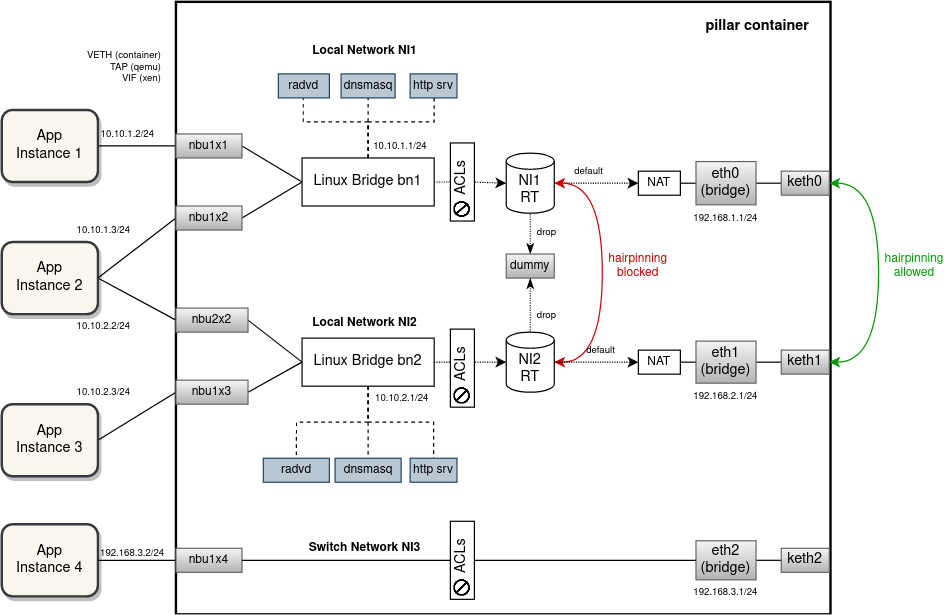
Note that the ACLs are mostly implemented on the network-instance side to provide drop and rate limiting, and also to mark packets for flowlog. There are a few iptables rules on the uplink (right) side to block some TCP/UDP ports from remote access etc.
While the current implementation is successful in prohibiting a direct communication between network instances and facilitating hairpinning inside or outside the device based on the aforementioned criteria, it fails to isolate networks when it comes to IP address allocation.
For example, it is not possible to deploy multiple network instances with the same or overlapping IP subnets. A significant risk of IP address collisions exists also between external (uplink) and internal (downlink) networks. A local network instance should be completely isolated and independent from the outside networks with a NAT placed in-between. Similarly, traffic selectors of multiple VPN networks could overlap, thus preventing from opening the tunnels at the same time, which is also against our semantics of network instance isolation.
We can get better separation, including IP address isolation if we split network instances using either VRFs or with network namespaces. Furthermore, if we use a containerd task to run network instance networking (especially the external processes like dnsmasq, radvd, etc.), we can even isolate resource usage and apply limiting. We will now describe VRFs and network instances separately, with a bit more focus on VRFs, which, after some internal discussion, are now the preferred choice.
VRF Proposal
VRF device combined with IP rules provides the ability to create virtual routing and forwarding domains (aka VRFs, VRF-lite to be specific) in the Linux network stack. VRF essentially provides a light-weight L3-level (and above) isolation, i.e. multiple interfaces can have the same IP address assigned if they are inside different VRF domains and, similarly, multiple processes can listen on the same IP address. Compare that with network namespaces, which provide a full device-level isolation, but at a cost of a higher overhead and with additional challenges for the management plane (see "Network Namespaces" below).
VRF is implemented as just another type of network device that can be created and described using the ip command. For every VRF, there is a separate routing table automatically created together with a special IP rule, matching packets with the corresponding VRF routing table. For an interface to enter a VRF domain, it has to be enslaved under the VRF device (just like interfaces are enslaved under a bridge). The main drawback of VRFs is that processes have to explicitly bind their sockets to the VRF in which they want to operate. This, however, can be solved outside of those processes by hooking up into the socket() function call using LD_PRELOAD. Alternatively, ip vrf exec command can be used to bind a process with a VRF using some eBPF magic. We can also make upstream contributions and add native VRF support to applications that we need to run inside VRFs, i.e. dnsmasq and radvd (currently neither of those are VRF aware).
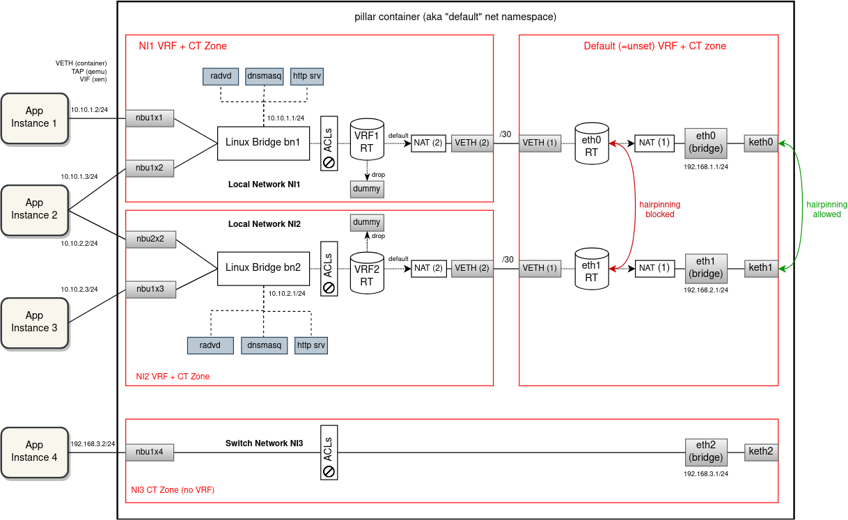
Diagram below shows how the separation of network instances using VRFs would look like. For every local/vpn network instance, zedrouter would create a separate VRF (automatically with its own routing table) and put the NI bridge under this VRF device. External processes providing network services separately for each NI, i.e. dnsmasq and radvd (and http server as a go routine of zedbox), would have their sockets bound to the VRF (most likely using 'ip vrf exec'). There will be no VRFs created for switch network instances. From EVE point of view these are L2-only networks.
Uplink interfaces would remain in the default (i.e. not configured) VRF domain and a VETH pair per NI would be used to interconnect the downlink (left) and the uplink (right) side (i.e. the left side of the VETH is enslaved under the NI VRF, while the right side remains in the default VRF domain). VETH interface will operate in the L3 mode - it will have IP addresses assigned on both ends from a /30 subnet. What supernet to allocate these subnets from is up to the discussion. It should be selected such that the risk of collision with other routed subnets is minimal. Already considered and tested are these special-purpose or reserved subnets: 0.0.0.0/8, 127.0.0.0/8, 169.254.0.0/16 and 240.0.0.0/4. However, only the last two turned out to be routable by the Linux network stack without issues.
Because we want to allow network instances to have overlapping IP subnets (between each other and with host networks), packet leaving NI VRF and entering the default VRF has to be S-NATed to the VETH IP. Given the presence of this VETH interface and the NAT rule, packets traveling between applications (deployed in local NIs) and external endpoints will be routed and NATed inside the pillar container twice. Similarly, port mapping ACL rules will have to be implemented as two D-NAT pre-routing rules, one for the uplink interface and the second for the corresponding VETH interface.
There will be no VETH links between VRFs of network instances. The current behavior of applications from different networks not being able to talk to each other directly will be preserved (and enforced with stronger measures). Hairpinning through portmaps will remain as the only option for communication for network-separated applications. In the default VRF domain there will be one routing table per uplink interface. Using ip rules each network instance will be matched with the RT of the uplink that was selected for that network by the configuration/probing. Network instances that use different uplinks at a given moment will be completely isolated from each other, not even sharing any RT along the routing path. Consequently, connections between uplink-separated NIs can only be established by hairpinning outside the edge device (through portmaps).
The implementation of ACLs is not going to undergo any significant changes, the existing iptables rules will remain pretty much the same (aside for the two DNAT rules for each portmap). However, using only VRFs is not enough for isolation when NAT and connection marking is being used (for ACLs and flowlog). It is necessary to also separate conntrack entries between different VRF domains to avoid collisions with overlapping IP addressing. This can be easily accomplished using conntrack zones (conntrack entries split using integer zone IDs). A NI-specific conntrack (CT) zone is used in-between the bridge and the NI-side of the VETH (same scope as that of the NI VRF). For the default routing table (between uplinks and the uplink-side of VETHs), we could leave the default CT zone 0. However, experiments showed that when VRF devices are being used the default CT zone stops working correctly, resulting in skipped iptables rules and some strange behaviour. Using any non-zero CT zone seems to fix the issue (see PoC section below).
In the diagram below, each separate VRF domain (combined with its own CT zone) is outline and highlighted using a red rectangle.
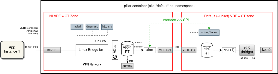
Special attention should be given to VPN networks. For the most part, these networks would be extended with VRFs just like the local network instances. However, for strongSwan (IKE daemon) to operate in multi-VRF mode, we have to switch to Route-based VPN mode. Using a special XFRM device (an enhanced alternative to VTI device), it is possible to bind an IPsec tunnel with a VRF domain as shown in the diagram below.
A single strongSwan process will continue operating for all VPN network instances. For every VPN NI there will be a separate XFRM device created inside the NI VRF, linked with the corresponding IPsec connection configuration using XFRM interface ID. Packet sent from application will be routed by the VRF routing table via the associated XFRM device, which then determines which SAs to use for encryption. An encrypted (and encapsulated) packet then continues through the VETH pair into the default VRF domain where it is routed out by the uplink RT. In the opposite direction, the SPI field of the encrypted packet will link to the XFRM device and thus the VRF where the decrypted packet should be inserted into for forwarding (i.e. VETH is skipped in this direction).
With this, it will be possible to deploy multiple VPN network instances with overlapping traffic selectors and still route/encrypt/decrypt unambiguously.
Network Namespaces (alternative proposal)
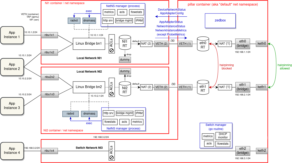
An alternative solution to VRFs is that instead of using per-NI VRF and CT zone, we could isolate on all network levels and run each Linux bridge and associated network interfaces plus external processes (dnsmasq, radvd, strongSwan ...) in a separate network namespace. For every new network instance zedrouter would create a new named network namespace (alternatively it could start a new containerd task with its own network namespace), connected with the "default" net namespace using a VETH pair. Downlink interfaces have to be moved into the target network namespace before they are put under the bridge. The bridge part is currently done by hypervisors (veth.sh for containers, qemu & xen allow to specify bridge in the domU config). This would be removed and we would instead finalize downlink interface configuration ourselves in doActivateTail() of domain manager.
For the most part, this is very similar to the VRF proposal, in that both solutions use VETHs to route and NAT packets from/to apps twice. Also, PBR routes/rules and iptables are very much the same, just spread across multiple namespaces.
The advantage of having multiple namespaces is a stronger isolation and not having all routes and iptables crammed in one network stack. Also, this solution is completely transparent to processes (like dnsmasq, radvd, etc.). The major downside of this solution is a higher overhead, in particular the increased memory footprint of the management plane as it is split into multiple processes (see below why it is needed). Also debugging will be somewhat more difficult. For example, for packet tracing one has to first switch to the proper network namespace or trace packets across multiple namespaces at once.
However, from the management-plane point of view this proposal is considerably more difficult to implement than VRFs. Working with multiple namespaces from the same process (e.g. zedbox) is possible but quite challenging. While each process has its own "default" namespace where it has started, individual threads can be switched between namespaces as needed. However, frequent switching between namespaces adds some overhead and it makes development and debugging even harder than it already is. For this reason, most network-related software products, including strongSwan for example, are intentionally not able to manage multiple network namespaces from a single process instance.
In Golang this is even more challenging since Go routines are provided instead of threads. Because Go routine can travel between threads as it executes, it can potentially change namespace mid-execution. It is possible to lock a Go routine with its current thread, but any Go routine spawned from inside will start back at the process default namespace. This gotcha is nicely described here.
And so while switching to another namespace, locking the thread, doing something quick (not asynchronous, e.g. listing conntracks) and immediately switching back is safe, running a long asynchronous task (e.g. tcp server, packet capture) has the risk of having some Go sub-routines escaping the namespace, which leads to some obscure bugs.
In general, it is recommended to spawn a new child process for every network namespace that needs to be operated in. For this reason, this proposal will follow up on the “Bridge Manager” described here.
The main idea of Bridge Manager is to split an overloaded zedrouter and run management of every network instance in a separate Go routine. In this proposal we would go even further and suggest to run Bridge Manager (here called "NetNS manager" because it would manage an entire namespace) as a child process of zedbox (or as a separate containerd task). The main communication mechanism of EVE - pubsub - is already prepared for interprocess messaging.
Splitting the management plane into multiple processes increases overhead and for edge devices the most concerning is the memory footprint. Experimentally, it was estimated that the size of the NetNS binary would be around 22 MB.This was done simply by creating a Go binary importing all packages that are expected to be needed. Please note that this is only a subset of total process RSS. The rest is harder to estimate without fully implementing the NetNS manager. Given that we should support up to 256 network instances, this quickly adds up to hundreds of megabytes of extra memory usage.
The following diagram shows how network instances could be isolated from each other using network namespaces. As it can be seen, not only the network configuration is spread across namespaces, but also the management plane is split into multiple processes (all of which increases complexity and overhead, thus making this proposal less appealing).
Proof of Concept
In order to verify that the proposed network configuration would actually work for all scenarios as intended, a PoC based on docker containers representing network stacks of (mock) apps, network instances and zedbox has been prepared. The source code for the PoC with diagrams and description can be found in this repository: https://github.com/milan-zededa/evenet
The idea was to come up with the simplest scenario (edge device configuration) that exercises all important network use-cases that EVE has to support (i.e. all types of network instances, all possible routing paths, all kinds of ACLs, etc.) and includes some overlapping subnets so that network isolation is a requirement. Then using docker containers we simulate all network stacks present in the scenario and run shell scripts that create the same network configuration that EVE would apply if this proposal was implemented. With this we can quickly and easily validate the proposed network configuration changes before commencing any implementation work in the EVE repository.
The scenario that PoC simulates consists of 6 apps and 6 network instances (3 locals, 2 vpns and 1 switch), with some overlapping subnets and some ACLs defined on top of that. A detailed description of the scenario can be found in the top-level README file of the PoC repository. There is a PoC implementation with VRFs as well as with network namespaces, so that the two proposals can be compared and an informed decision which one to choose can be made.
Both PoCs successfully implement the scenario and pass all devised tests, overcoming the challenge of network IP subnet and VPN traffic selector collisions (see here and here). Notice that tests also cover hairpinning inside and outside the device (which one to do depends on whether src and dst NIs use the same uplink). The reason why we prefer to use VRFs, is their lower footprint and the fact that they are easier to manage.
For VETHs, subnets 127.0.0.0/8 and 0.0.0.0/8 sadly failed the validation - routing does not work as expected/desired (even if the local table is tweaked in various ways). On the other hand, 169.254.0.0/16 and 240.0.0.0/4 can be routed between network namespaces and VRFs without issues. But for 169.254.0.0/16 we need to select a subnet that does not contain 169.254.169.254, which is already used for the HTTP server with cloud-init metadata. After some internal discussion, we are more inclined to allocate VETH IPs from the (most likely) forever-reserved Class E subnet 240.0.0.0/4.
Development Steps (VRF Proposal)
PR 1:
	* Build Linux kernel with VRF support

PR 2:
	* LD-PRELOAD library for VRF-unaware processes
	    - or test 'ip vrf exec' as an alternative

PR 3:
	* Eden test for local networks with overlapping IP subnets
		- without VRFs this test will be failing (i.e. would not be merged until PR 4 is done)

PR 4:
	* Local & Switch Network instance (Create/Modify/Delete)
	* ACLs
	* Flow collection
	* Network instance metrics

PR 5:
	* Eden test for VPN networks with overlapping traffic selectors
		- without VRFs this test will be failing (i.e. would not be merged until PR 6 is done)

PR 6:
	* VPN Network instance
3 Comments
Erik Nordmark
Looks very good; thanks for all the details.
A nit on the drawings: we apply ACLs on the left as well e.g., by default nbu1x1 and nbu1x2 can not communicate unless there are allow ACLs specified.
Note that currently EVE-OS only allows one IPsec vpn i.e., only one cloud network instance. Sounds like with this approach we can remove this restriction.
The switch network instance (the eth2 bridge above) typically doesn't have an IP address, but if it does as in your drawings, how are application instances on the switch NI prevented from using the default VRF routing table to communicate with EVE? (And would iut make sense to put the switch NI in a vrf even if it has no IP addresses configured?)
Erik Nordmark
Would it make sense to note that the 240.0.0.0 IP addresses might appear in traceroute output?
Milan Lenco
OK, so apparently I do not get notified when someone comments on my page. Sorry Erik Nordmark for a late response...
> A nit on the drawings: we apply ACLs on the left as well e.g., by default nbu1x1 and nbu1x2 can not communicate unless there are allow ACLs specified.
True, I need to improve the drawing here to cover this case as well.
> The switch network instance (the eth2 bridge above) typically doesn't have an IP address...
This is a mistake in the drawing indeed. If we decide to put IP address on the bridge anyway, I would then suggest to isolate it using a VRF. Without a VETH-pair it will not be able to access the default VRF of EVE.
> Would it make sense to note that the 240.0.0.0 IP addresses might appear in traceroute output?
Yes, let's mention it in the documentation if/once implemented.